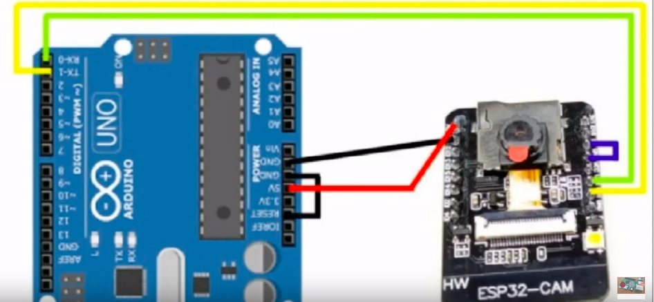

(TX is here from Arduino to camera and RX camera to Arduino) A pair of wires with RS485 bidirectionalįirst of all we need to configure the camera via the dip switch, we have 3 possible modes: My vacation is now over, I had a little tchat with my teacher and we figured out that the most "easy" way to have multiple cameras without denuding the already present wires is to have: The 2 modules that generates RS485 works with the 2 mains architectures (avr and esp32) I had keypad laying around my place so I plugged him in the esp and onto the testing and good news! What do we do with a functionning library, we test it! I swear the title is not a Clint Eastwood reference O_O Pgm_read_byte(&DATA1) //(Demo purpose not in the lib) While Intellisense keeps throwing error because it's a bit dumb (don't worry I fixed) Ok problem fixed The solution: After reading a bit of documentation, you actually need to do this: Why? Because progmem is maintained by a library: pgmspace.h (more on the arduino refenrece) If I want to compare the Command PAN_L to DATA1, I can't use a loop with DATA1 (with i incrementing) The problem: Getting a value of progmem's flash isn't what it is. The solution: have a list with every special case! const byte CMND1 PROGMEM = //will I use it?

Ok so to resume, the lib need to know which command we are sending to correctly parse the input data (e.g: if the command is SET_PAN, the lib must compute the given angle to hex values to transmit) Arduino administration is simpler than France oneĦ hours of debugging can save you 5 minutes of reading documentation.The camera, the keypad and the computer.6 hours of debugging can save you 5 minutes of reading documentation.As, slow microcontrollers have less processing time adding more delay between capturing frames.Hello and welcome back to a project log! I would first thank you all for following me in this project and huge thanks to Arsenijs Picugins who made an article about RS485 which is very well documented Also add required delay depending upon the microcontroller frequency we are using. The register values need to be changed from the default to the custom. To initialise the camera, we only have the options to change the register values. arduinoUnoInut() Īfter configuring the Arduino, the camera has to be configured. Initially it disables all the global interrupts and sets the communication interface configurations such as the PWM clock, selection of interrupt pins, presclaer selection, adding parity and stop bits. The first function is arduinoUnoInut() which is used to initialise the arduino uno. The Setup() comprises all the initial setups required for only image capturing. We just have to include the libraries to get the job done.Īfter this, the registers need to be modified for OV7670. The libraries used in this project are built-in libraries of ArduinoIDE. Since OV7670 runs on I2C interface, it includes library.

I have used following program written in C++.
#Arduino camera code serial#
You can use any program of your choice or write your own serial port reader.
#Arduino camera code code#
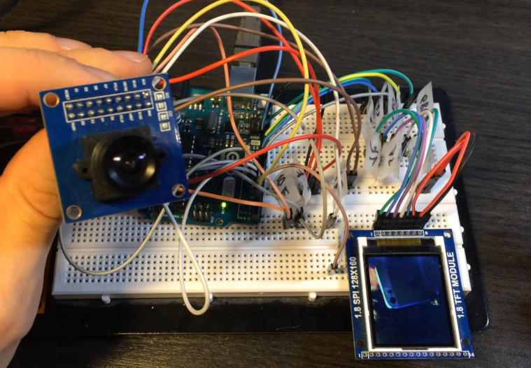
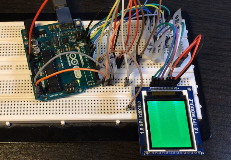
Once you connect the arduino and camera module as per the above diagram compile the code mentioned below and upload to Arduino uno.Īfter that you will need an output program to convert the raw data read by the Arduino through the serial port into an image. OV7670 Arduino Camera Sensor Module STM32.The pin outs of the module are as follows: Saturation level auto adjust (UV adjust).Image quality controls including color saturation, hue, gamma, sharpness (edge enhancement), and anti-blooming.Exposure Control (AEC), Automatic Gain Control (AGC), Automatic White Balance (AWB), Automatic Band Filter (ABF), and Automatic Black-Level Calibration (ABLC).Automatic image control functions including: Automatic.High sensitivity for low-light operation.Mounted with high quality F1.8 / 6mm lens.Onboard regulator, only single 3.3V supply needed.

The OV7670 camera module built-in onboard LDO regulator only requires single 3.3V power and can be used in Arduino, STM32, Chipkit, ARM, DSP,FPGA and etc. The camera module is powered from a single +3.3V power supply, and external clock source for camera module XCLK pin. It provides full-frame, sub-sampled or windowed 8-bit images in various formats, controlled through the Serial Camera Control Bus (SCCB) interface. The OV7670 image sensor is a small size, low voltage, single-chip VGA camera and CMOS image processor for all functions.


 0 kommentar(er)
